During the __________ Phase of Separation
![]()
Solidification Behavior of Polymer Solution during Membrane Preparation by Thermally Induced Stage Separation
Heart for Membrane and Film Technology, Section of Chemical Engineering, Kobe Academy, ane-one Rokkodai, Nada-ku, Kobe 657-8501, Japan
*
Author to whom correspondence should exist addressed.
Received: 10 January 2014 / Revised: ten February 2014 / Accepted: 14 February 2014 / Published: 28 February 2014
Abstract
The solidification behavior of poly(vinylidene fluoride) (PVDF) solution during membrane training by thermally induced phase separation (TIPS) was investigated. Apparatus newly developed in our laboratory was used to quantitatively measure membrane stiffness during stage separation. In this apparatus, a cooling polymer solution, placed on a stage, is moved upward and the surface of the polymer solution contacts a sphere attached to the tip of a needle. The deportation of a blade spring attached to the needle is so measured by a laser deportation sensor. Different phase separation modes, such as liquid-liquid (L-50) phase separation and solid-liquid (S-Fifty) phase separation (polymer crystallization) were investigated. In the case of S-L phase separation, the stiffness of the solution surface began to increase significantly just before termination of crystallization. In contrast, L-L phase separation delayed solidification of the solution. This was considering mutual contact of the spherulites was obstructed by aerosol of polymer-lean phase formed during L-Fifty phase separation. Thus, the solidification charge per unit was slower for the L-L stage separation system than for the S-L phase separation system.
1. Introduction
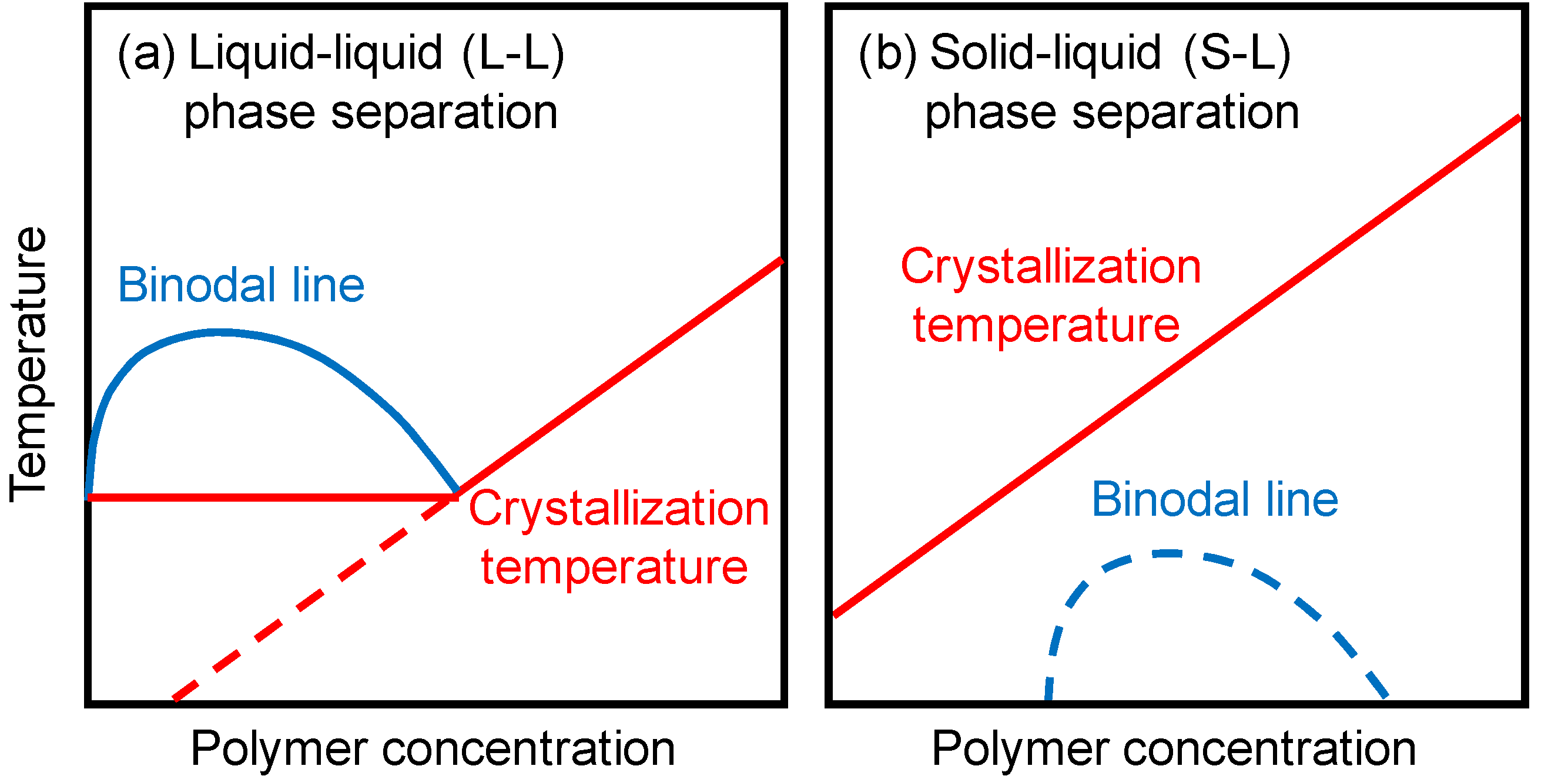
Polymeric porous membranes are by and large prepared past phase separation of polymer solutions [1]. Phase separation can be induced by cooling or past the presence of nonsolvent. The sometime is thermally induced phase separation (TIPS), while the latter is nonsolvent induced phase separation (NIPS). In membrane grooming by TIPS, a polymer is dissolved in a diluent at high temperature, and so the homogeneous polymer solution is cooled to induce the stage separation. Later on the polymer is solidified by crystallization or glass transition, the diluent is extracted by solvent exchange and the extractant is unremarkably evaporated to yield a microporous structure. At that place are ii main types of phase separation for the crystalline polymers commonly used in the TIPS procedure. When the binodal line, which is the border between homogeneous solution and phase-separated solution, is located above the crystallization temperature, liquid-liquid (50-L) stage separation occurs. The stage diagram in this case is shown in Effigy 1a. The solution separates into a polymer-rich continuous phase and a polymer-lean droplet stage. On the other hand, if the crystallization temperature is higher than the binodal line, solid-liquid (S-L) phase separation (i.eastward., polymer crystallization) occurs (Figure 1b). Many central thermodynamic and kinetic studies take been done on membrane formation via TIPS [2,3,4,five,half dozen,7,8,9,10].
Figure i. Phase diagrams in the thermally induced phase separation (TIPS) method. (a) Liquid-liquid (L-50) phase separation; (b) Solid-liquid (S-Fifty) phase separation.
Figure i. Phase diagrams in the thermally induced phase separation (TIPS) method. (a) Liquid-liquid (L-L) stage separation; (b) Solid-liquid (S-L) stage separation.
A large number of microporous membranes with a diverseness of morphologies have been prepared from various polymers, including poly(vinylidene fluoride) (PVDF) [xi,12], polyethylene [thirteen,xiv], polypropylene [fifteen,16], poly(methyl methacrylate) [17,18], polystyrene [xix] and poly(ethylene-co-vinyl alcohol) [xx,21], by TIPS. In particular, PVDF, which is a semi-crystalline polymer, has wide applications in manufacture of microfiltration (MF) and ultrafiltration (UF) membranes because of its splendid properties such as good mechanical strength, stability against aggressive chemicals and good thermal stability. PVDF microfiltration membranes prepared past the TIPS method have been commercially practical in drinking-water production and wastewater handling.
Many studies of porous polymer membranes take focused on the prevention of membrane fouling and on improvement of membrane performance (such every bit solute rejection and water permeability), which directly affect the efficiency of water-treatment processes. Although the solidification behavior of a polymer solution during the phase separation process significantly affects the membrane preparation process, very few studies have reported solidification behavior of a polymer solution during the stage separation procedure. Understanding the solidification behavior of the polymer solution allows i to optimize the take-up speed of membrane training and the design of the coagulation (cooling) bath and rollers. Bonyadi et al. [22] and Yin et al. [23] indicated that the solidification rate affects the morphology of hollow fiber membranes prepared past NIPS.
In our previous study, nosotros developed a new apparatus for direct measuring membrane stiffness and quantitatively analyzed the solidification behavior of polymer solutions during the NIPS process [24]. The effects of polymer concentration, limerick of the coagulant, molecular weight of polymer and additives were investigated using this appliance. Addition of hydrophilic additives to the polymer solution significantly accelerated the solidification rate because the uptake of water into the polymer solution was enhanced.
The aim of the nowadays study was to investigate the solidification characteristics of polymer solutions during the TIPS process using this appliance. Furthermore, nosotros attempted to clarify the correlations betwixt the solidification and crystallization behaviors of polymer solutions. The effects of stage separation patterns such every bit S-50 and L-L stage separations on the solidification characteristics were investigated. The polymer examined was PVDF, chosen because PVDF membranes have been widely used commercially, equally described above. As far as we know, this is the first work on the solidification characteristics of polymer solutions during the TIPS process.
ii. Results and Give-and-take
two.1. Phase Separation Behavior
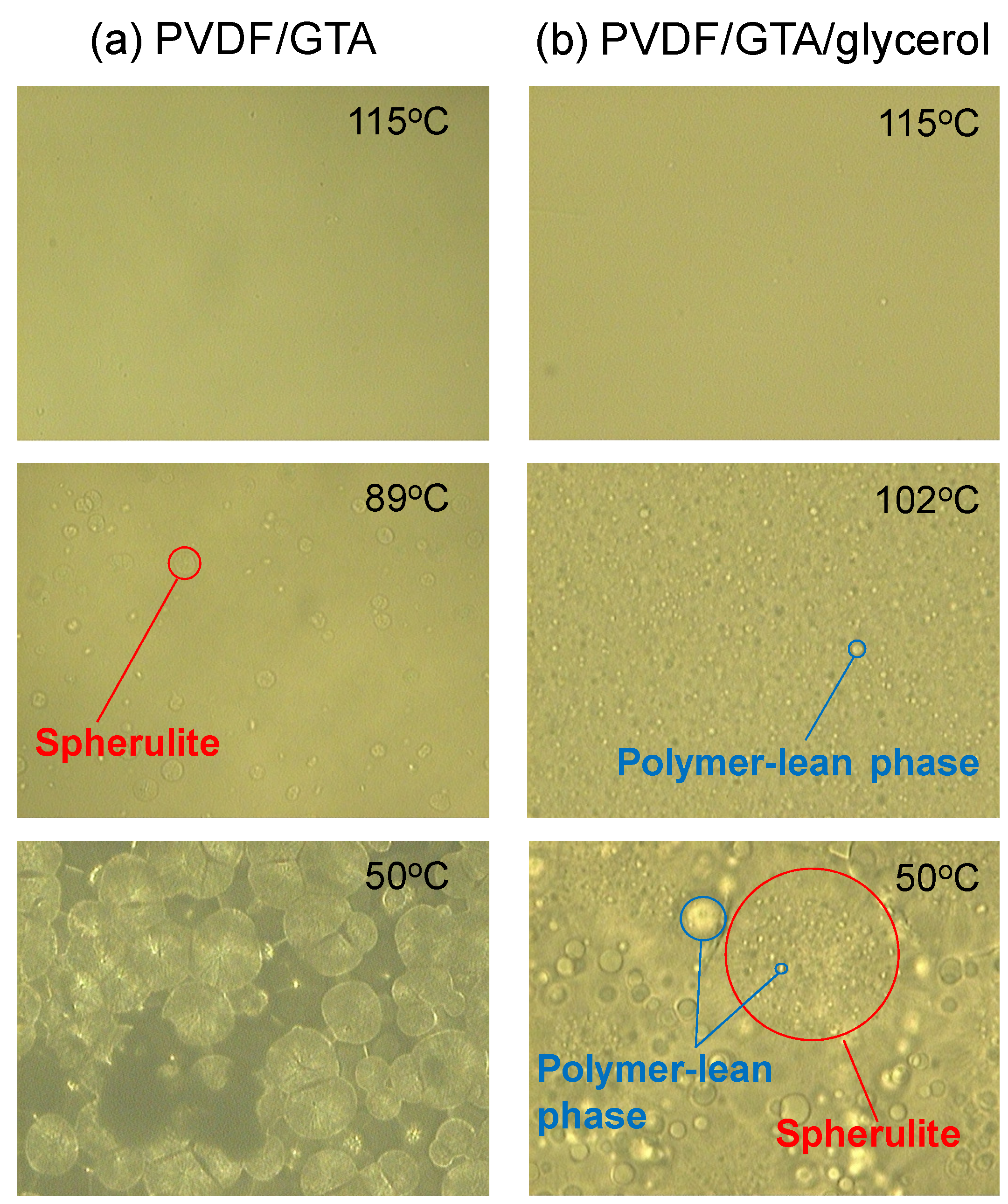
Figure 2a shows optical micrographs of a PVDF (thirty wt %)/Glycerol triacetate (GTA) (70 wt %) solution at various temperatures in the cooling procedure. Spherulite formation is clearly observed. In this arrangement, the compatibility betwixt PVDF and GTA is loftier, which results in a shift of the binodal line to below the crystallization temperature. Thus, polymer crystallization (Southward-50 phase separation) occurs [25]. The micrographs show that isolated spherulites formed first, and then grew before finally contacting each other. Similar Due south-Fifty phase separation was observed for the PVDF (thirty wt %)/diethyl phthalate (DEP) (70 wt %) organisation. The dynamic crystallization temperatures (T c), at a cooling rate of 10 °C/min, for PVDF (30 wt %)/GTA (70 wt %) and PVDF (thirty wt %)/DEP (70 wt %) solutions were 89 °C and 100 °C, respectively. The solubility parameters of PVDF [26], GTA and DEP [27] are 23.2 MPa0.5, 22.0 MPa0.5 and 20.4 MPa0.5, respectively. The solubility parameter of GTA is closer than that of DEP to that of PVDF. Therefore, the compatibility betwixt PVDF and GTA is higher. When the compatibility is high, the crystallization temperature of the polymer solution decreases [3]. Thus, a lower crystallization temperature was obtained for the PVDF/GTA system.
The phase separation behavior of the PVDF (xxx wt %)/GTA (threescore wt %)/glycerol (10 wt %) organisation is shown in Figure 2b. Many aerosol of polymer-lean phase were firstly formed by 50-L phase separation. This is because the add-on of glycerol (nonsolvent) lowered the compatibility between the PVDF and the solvent mixture, and shifted the binodal line to temperatures to a higher place the crystallization temperature [25]. The solubility parameter of glycerol is 36.2 MPa0.5 [27], which is far from that of PVDF (23.ii MPa0.five) [26]; glycerol is a nonsolvent for PVDF. Even in this system, spherulites formed after and grew.
Figure 2. Optical micrographs during phase separation. (a) poly(vinylidene fluoride) (PVDF) (xxx wt%)/glycerol triacetate (GTA) (seventy wt%) system; (b) PVDF (30 wt %)/GTA (60 wt %)/glycerol (10 wt %) system.
Effigy 2. Optical micrographs during phase separation. (a) poly(vinylidene fluoride) (PVDF) (thirty wt%)/glycerol triacetate (GTA) (seventy wt%) system; (b) PVDF (thirty wt %)/GTA (sixty wt %)/glycerol (10 wt %) arrangement.
ii.2. Solidification Beliefs of Polymer Solution during TIPS Process
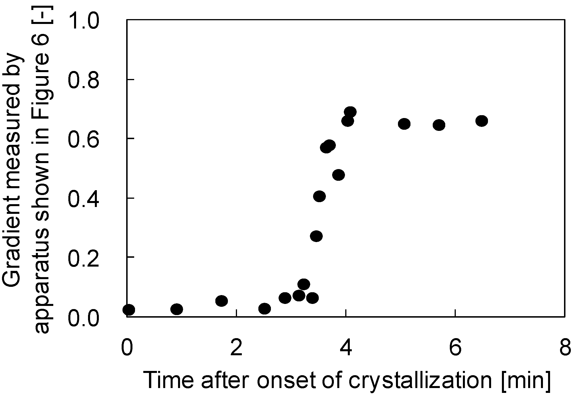
Figure 3 shows the gradients of the plots of needle deportation against stage displacement versus fourth dimension afterwards the onset of crystallization. In this experiment, a PVDF (30 wt %)/GTA (70 wt %) solution was used. In the commencement, just after the onset of the crystallization, the gradients were virtually goose egg. This means that the polymer solution was still soft and the sphere attached to the tip of the needle could easily penetrate into the polymer solution. This is reasonable, because in the initial stages of crystallization, the formed spherulites are dispersed in the solution and are not in contact with each other, as shown in Figure 2a; therefore the surface of the polymer solution is not so hard. Later on virtually 3 min, the gradient increased sharply before reaching a abiding value. This increase in gradient probably begins when the spherulites begin to contact each other. Afterward the spherulites were completely in contact, the stiffness of the solution surface became constant and the gradients besides showed a abiding value. The terminal abiding gradient value obtained in this case was about 0.65; this value is lower than unity, suggesting that the solution surface was not completely hardened, even after the termination of crystallization.
Figure 3. Variation of the ratio of the needle displacement to stage displacement with time afterwards the onset of crystallization in the PVDF (30 wt %)/GTA (70 wt %) arrangement.
Figure 3. Variation of the ratio of the needle displacement to phase deportation with time later on the onset of crystallization in the PVDF (xxx wt %)/GTA (70 wt %) system.
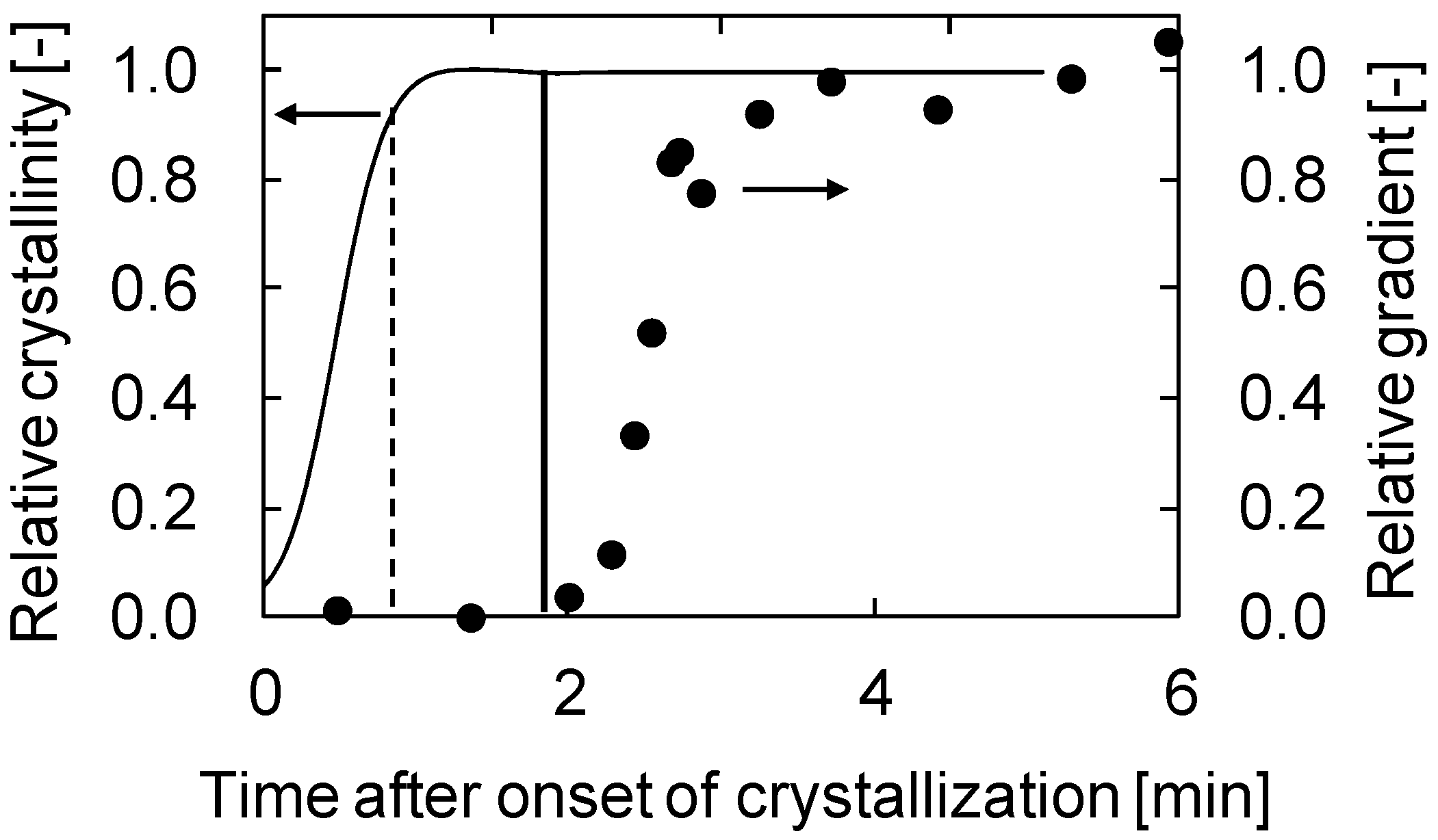
The comparison betwixt the relative gradient and the relative crystallinity obtained by differential scanning calorimetry (DSC) is shown in Figure 4a. The relative gradient and crystallinity were normalized to the final slope and crystallinity, respectively. The relative crystallinity shows a sigmoidal curve. In each effigy, the fourth dimension for the start of the slope increase is shown past a vertical line. This fourth dimension corresponds to the time just earlier the relative crystallinity became unity. This shows the stiffness of the solution surface started to increase significantly but before the termination of crystallization, that is, when common contact of the spherulites occurred. Thus, the result obtained in this work clearly indicates that the fourth dimension the crystallization starts is non important for generation of stiffness of a phase separating solution; instead, the time when crystallization ends determines the solution stiffness.
Figure 4. Comparison between relative gradient and relative crystallinity. (a) PVDF (30 wt %)/GTA (70 wt %) system; (b) PVDF (thirty wt %)/DEP (lxx wt %) system.
Figure 4. Comparison betwixt relative slope and relative crystallinity. (a) PVDF (xxx wt %)/GTA (70 wt %) system; (b) PVDF (thirty wt %)/DEP (70 wt %) system.
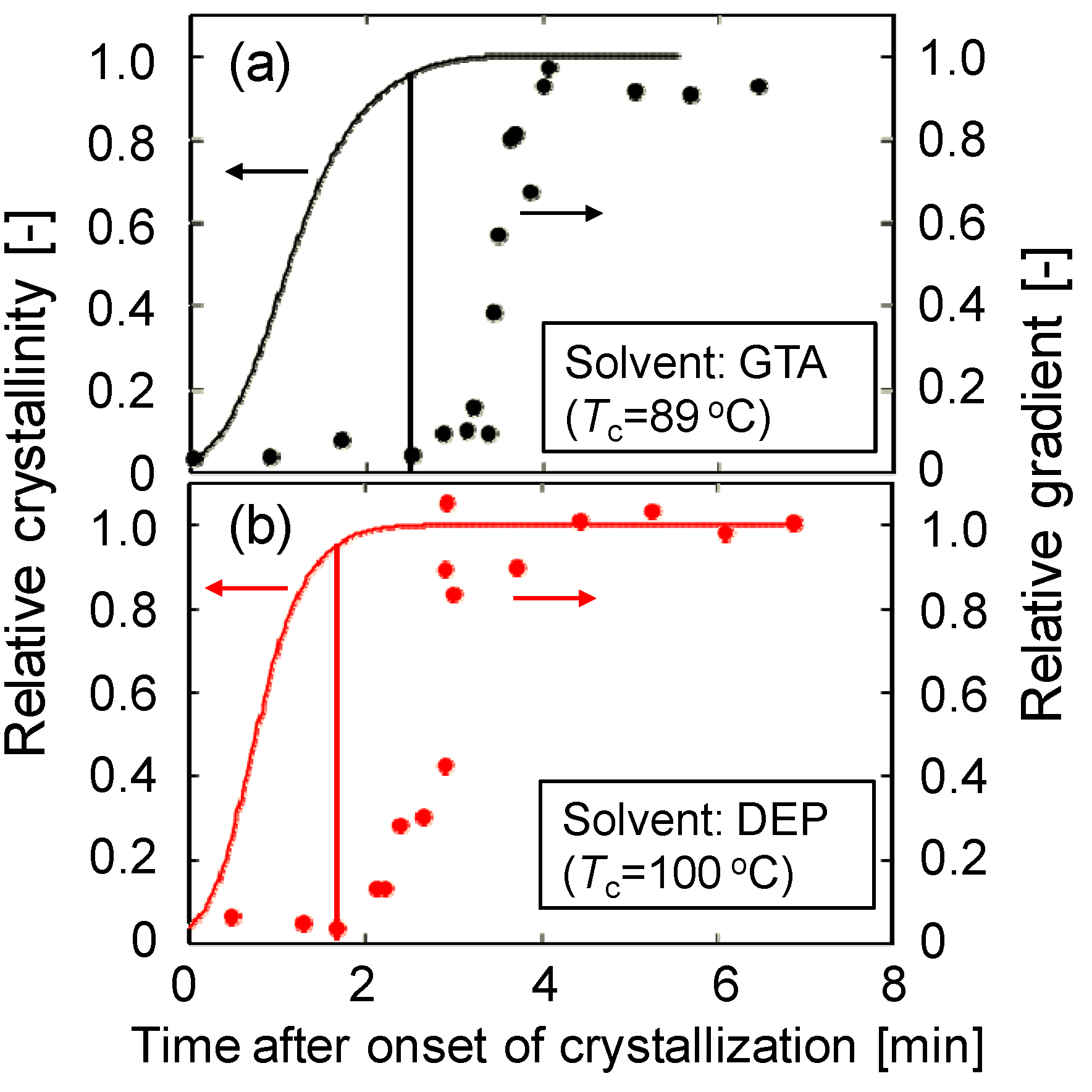
Figure 4b shows the time courses of relative gradient and relative crystallinity for the PVDF/DEP organization. Equally described above, the dynamic crystallization temperature (100 °C) of PVDF (thirty wt %)/DEP (70 wt %) solution was higher than that (89 °C) of PVDF (30 wt %)/GTA (70 wt %) solution. Comparison Figure 4a,b, the relative crystallinity reached its final value at around 3.5 min afterwards onset of crystallization in the example of the PVDF/GTA system, while the relative crystallinity reached at 2.5 min in the instance of the PVDF/DEP organisation, explaining that the crystallization occurred more chop-chop in the PVDF/DEP system than in the PVDF/GTA arrangement. This is because the polymer chain move is higher equally a result of the college crystallization temperature. Although the crystallization temperature was unlike, the same decision—that the stiffness of the solution surface began to increment significantly just before the termination of crystallization—was also obtained for the PVDF/DEP system. Thus, this conclusion is probably valid for all South-50 type phase separation systems.
Figure 5 shows the results for the PVDF (30 wt %)/GTA (60 wt %)/glycerol (ten wt %) system. As shown in Effigy 2b, L-Fifty stage separation occurred in this solution. The binodal temperature and the crystallization temperature were 120 and 99 °C, respectively. In this case, the solidification of the solution surface did not start merely before the termination of crystallization, but instead began some time after termination of crystallization. The fourth dimension expected for the get-go of the gradient increase, based on the relative crystallinity value at which the Southward-50 stage separation system showed an increase, is shown past the dotted line. Conspicuously, the observed time (solid line) is longer than the expected fourth dimension (dotted line). In the case of L-L phase separation, droplets of polymer-lean phase exist between the spherulites, as shown in Figure 2b. Thus, mutual contact of the spherulites is not likely to occur, considering of obstruction by the droplets. This is why solution stiffness increase began later in this system. Therefore, the solidification rate is slower for the L-Fifty stage separation organisation than for the Due south-Fifty phase separation organization.
Figure 5. Comparison between relative slope and relative crystallinity in PVDF (30 wt %)/GTA (60 wt %)/glycerol (10 wt %) organisation.
Figure five. Comparing between relative gradient and relative crystallinity in PVDF (30 wt %)/GTA (60 wt %)/glycerol (10 wt %) system.
3. Experimental Section
3.1. Materials
PVDF, Mw = 136,000 (Solef 6008; Solvay Avant-garde Polymers Co., Alpharetta, GA, The states) was used in the membrane preparation. Glycerol triacetate (GTA) and diethyl phthalate (DEP) were used as solvents and glycerol was used every bit the nonsolvent. These were purchased from Wako Pure Chemical Industries (Osaka, Nippon) and used without further purification.
three.two. Crystallization Behavior
A DSC (DSC-seven, PerkinElmer Inc., Waltham, MA, USA) was used to determine the dynamic crystallization temperature at a constant cooling rate. The mixture of solid polymer and solvent/nonsolvent was sealed in an aluminum DSC pan, melted at 190 °C for 5 min and so cooled at 10 °C/min to 30 °C. The onset of the exothermic acme during the cooling was taken as the crystallization temperature.
The crystallinity of the polymer solution at time t after the onset of crystallization Ten c (t) was evaluated past the post-obit equation:
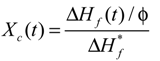
where  is the melting enthalpy for 100% crystalline PVDF, 104.v J/g [28], ΔHf (t) is the melting enthalpy of the solution at time t afterward the onset of crystallization, as measured by DSC, and φ is the weight fraction of PVDF in the solution.
three.3. Ascertainment of Phase Separation
The polymer-solvent-nonsolvent samples were placed betwixt a pair of microscope encompass slips. A Teflon flick, 100 µm thick, with a foursquare opening, was inserted betwixt the encompass slips. The sample was heated on a hot stage (LK-600PH, Linkam Scientific Instruments Ltd., Surrey, Great britain) at 150 °C for 2 min and cooled to 30 °C at a controlled rate of 10 °C/min. The temperature of the stage was manipulated by a Linkam L-600A controller (Linkam Scientific Instruments Ltd., Surrey, UK). The phase separation beliefs was observed under an optical microscope (BX50, Olympus Corporation, Tokyo, Japan).
3.4. Membrane Stiffness Measurement
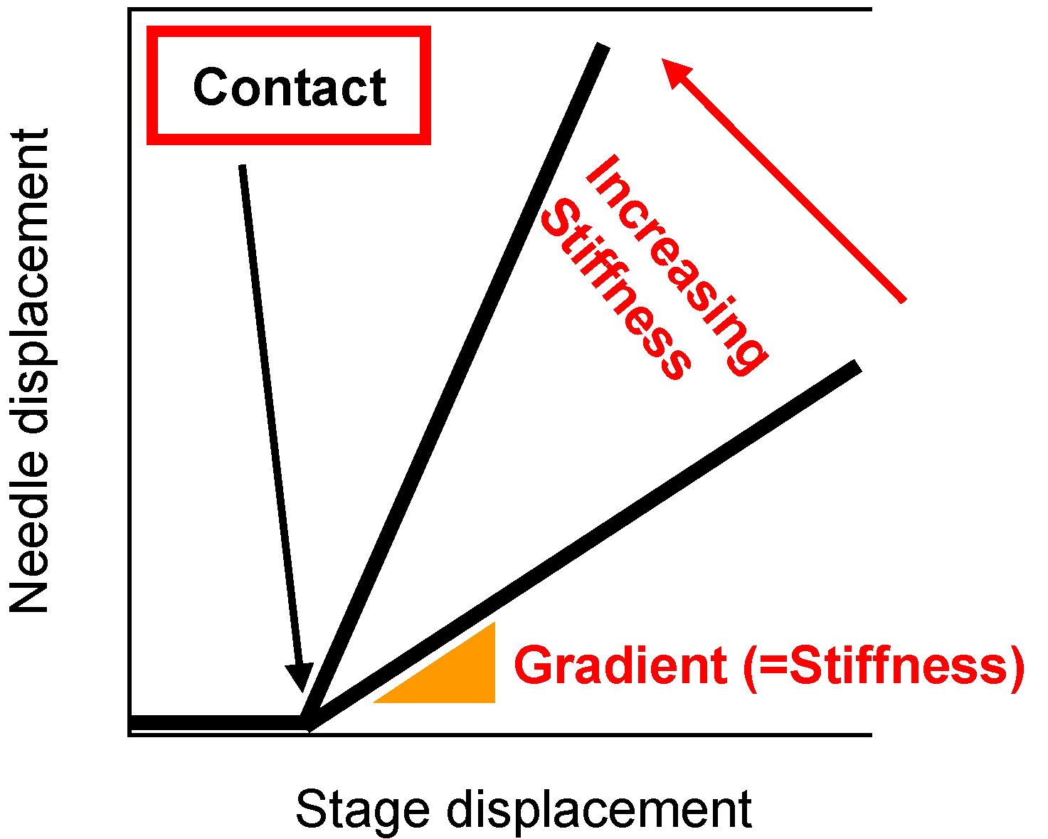
Effigy half-dozen shows a diagram of the stiffness measurement apparatus. This apparatus was the same as that used previously in our laboratory [24]. The hot stage (LK-600PH, Linkam Scientific Instruments Ltd., Surrey, UK) was placed on the movable stage. The hot homogeneous PVDF solution was poured into a washer (thickness 1.4 mm) on a stainless steel canvass (thickness: 0.08 mm) on the hot stage controlled at 150 °C. So the sample was cooled downward past the Linkam L-600A controller to induce phase separation. The phase was moved upward at 50 µm/s and the surface of the polymer solution during phase separation contacted a sphere attached to the tip of a needle. The displacement of a blade jump fastened to the needle was measured past a laser displacement sensor. The needle displacement was plotted confronting stage deportation. When the solution has low stiffness, the gradient of the plot of needle displacement against stage deportation is almost zero, because the sphere attached to the needle goes easily into the solution. On the other hand, when the sample is sufficiently hard, this gradient is close to unity and the stage displacement is equal to the needle displacement. Thus the gradient represents the stiffness of the solution [24]. The concept of this slope in the plot of the needle displacement against the stage displacement is shown in Figure 7. From each cooling experiment, merely one gradient data bespeak was taken, simply after the contact betwixt the sphere and the solution surface. Therefore, slope data at various times afterward onset of the polymer crystallization were obtained by adjusting the fourth dimension at which solution cooling began.
Figure six. Schematic diagram of stiffness measurement apparatus.
Effigy half dozen. Schematic diagram of stiffness measurement apparatus.
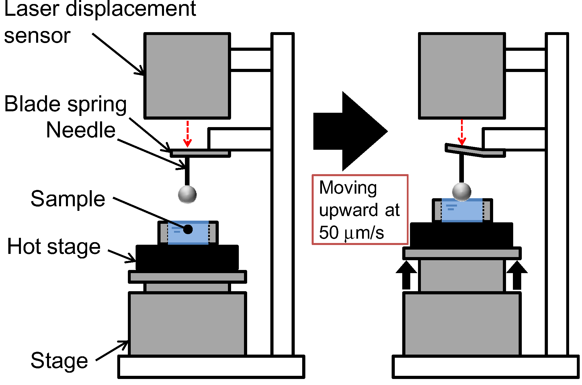
Figure 7. Concept of gradient in plot of needle deportation against phase displacement.
Figure 7. Concept of gradient in plot of needle displacement against stage displacement.
4. Conclusions
In this study, we quantitatively analyzed the solidification behavior of polymer solutions during the TIPS process by using the apparatus newly adult in our laboratory. In the instance of Southward-L phase separation (polymer crystallization), the stiffness of the solution surface began to increase significantly just before the termination of crystallization. At this time, the spherulites formed by the crystallization come into contact with one some other. In contrast, for Fifty-L phase separation, the solidification of the solution surface did non begin just earlier the termination of crystallization, but instead began some time after the termination of crystallization. This is because the mutual contact of the spherulites is obstructed by the aerosol of polymer-lean phase formed by L-50 stage separation. Thus, the solidification rate of the 50-50 phase separation organization during phase separation past the TIPS procedure was slower than that of the S-Fifty phase separation organization.
Acknowledgments
This work was supported, in role, past the Regional Innovation Strategy Support Plan, Ministry of Education, Culture, Sports, Science and Technology, Japan.
Conflicts of Interest
The authors declare no conflict of involvement.
References
- Mulder, M. Basic Principles of Membrane Technology, 2d ed.; Kluwer Academic Publishers: Dordrecht, The Netherlands, 1996; pp. 75–140. [Google Scholar]
- Caneba, G.T.; Soong, D.S. Polymer membrane formation through the thermal-inversion process: experimental written report of membrane structure formation. Macromolecules 1985, 18, 2538–2545. [Google Scholar] [CrossRef]
- Lloyd, D.R.; Kinzer, K.Due east.; Tseng, H.S. Microporous membrane formation via thermally induced phase separation. i. solid-liquid phase separation. J. Membr. Sci. 1990, 52, 239–261. [Google Scholar] [CrossRef]
- Tsai, F.J.; Torkelson, J.Thousand. Microporous poly(methyl methacrylate) membranes. Outcome of a depression-viscosity solvent on the formation mechanism. Macromolecules 1990, 23, 4983–4989. [Google Scholar] [CrossRef]
- Lloyd, D.R.; Kim, S.; Kinzer, K.E. Microporous membrane formation via thermally induced stage separation. ii. liquid-liquid phase separation. J. Membr. Sci. 1991, 64, 1–11. [Google Scholar] [CrossRef]
- Mehta, R.H.; Madsen, D.A.; Kalika, D.Due south. Microporous membranes based on poly(ether-ether ketone) via thermally-induced phase separation. J. Membr. Sci. 1995, 107, 93–106. [Google Scholar] [CrossRef]
- McGuire, G.S.; Laxminarayan, A.; Martula, D.S.; Lloyd, D.R. Kinetics of droplet growth in liquid-liquid phase separation of polymer-diluent systems. Model development. J. Colloid Interface Sci. 1996, 182, 46–58. [Google Scholar] [CrossRef]
- Matsuyama, H.; Berghmans, S.; Batarseh, G.T.; Lloyd, D.R. Effects of thermal history on anisotropic and asymmetric membranes formed by thermally induced stage separation. J. Membr. Sci. 1998, 142, 27–42. [Google Scholar] [CrossRef]
- Matsuyama, H.; Berghmans, S.; Lloyd, D.R. Formation of anisotropic membranes via thermally induced phase separation. Polymer 1999, 40, 2289–2301. [Google Scholar] [CrossRef]
- Matsuyama, H.; Kudari, Southward.; Kiyofuji, H.; Kitamura, Y. Kinetic studies of thermally induced phase separation in polymer-diluent system. J. Appl. Polym. Sci. 2000, 76, 1028–1036. [Google Scholar] [CrossRef]
- Ji, One thousand.L.; Zhu, L.P.; Zhu, B.One thousand.; Zhang, C.F.; Xu, Y.Y. Structure formation and characterization of pvdf hollow fiber membrane prepared via tips with diluent mixture. J. Membr. Sci. 2008, 319, 264–270. [Google Scholar] [CrossRef]
- Cui, Z.; Hassankiadeh, N.T.; Lee, S.Y.; Lee, J.M.; Woo, K.T.; Sanguineti, A.; Arcella, Five.; Lee, Y.M.; Drioli, E. Poly(vinylidene fluoride) membrane preparation with an environmental diluent via thermally induced stage separation. J. Membr. Sci. 2013, 444, 223–236. [Google Scholar] [CrossRef]
- Matsuyama, H.; Okafuji, H.; Maki, T.; Teramoto, Thou.; Kubota, N. Preparation of polyethylene hollow cobweb membrane via thermally induced phase separation. J. Membr. Sci. 2003, 223, 119–126. [Google Scholar] [CrossRef]
- Park, M.J.; Kim, C.M. Fabrication of polyethylene microporous membranes using triethylolpropane tris(ii-ethylhexanoate) as a novel diluent by a thermally induced phase separation process. J. Membr. Sci. 2014, 449, 127–135. [Google Scholar] [CrossRef]
- Lin, Y.M.; Chen, G.; Yang, J.; Wang, Ten.L. Formation of isotactic polypropylene membranes with bicontinuous structure and good force via thermally induced stage separation method. Desalination 2009, 236, 8–fifteen. [Google Scholar] [CrossRef]
- Vanegas, M.Eastward.; Quijada, R.; Serafini, D. Microporous membranes prepared via thermally induced stage separation from metallocenic syndiotactic polypropylenes. Polymer 2009, 50, 2081–2086. [Google Scholar] [CrossRef]
- Tsai, F.J.; Torkelson, J.Thou. Roles of phase separation mechanism and coarsening in the formation of poly(methyl methacrylate) asymmetric membranes. Macromolecules 1990, 23, 775–784. [Google Scholar] [CrossRef]
- Funk, C.V.; Beavers, B.L.; Lloyd, D.R. Effect of particulate filler on cell size in membranes formed via liquid-liquid thermally induced stage separation. J. Membr. Sci. 2008, 325, 1–5. [Google Scholar] [CrossRef]
- Song, S.West.; Torkelson, J.K. Coarsening furnishings on the germination of microporous membranes produced via thermally induced phase separation of polystyrene-cyclohexanol solutions. J. Membr. Sci. 1995, 98, 209–222. [Google Scholar] [CrossRef]
- Qiangguo, B.Fifty.; Yang, Y. The stage diagrams of mixtures of EVAL and PEG in relation to membrane formation. J. Membr. Sci. 2000, 180, 81–92. [Google Scholar] [CrossRef]
- Shang, Thou.; Matsuyama, H.; Maki, T.; Teramoto, M.; Lloyd, D.R. Effect of crystallization and liquid-liquid phase separation on phase-separation kinetics in poly(ethylene-co-vinyl alcohol)/glycerol solution. J. Polym. Sci. B Polym. Phys. 2003, 41, 194–201. [Google Scholar] [CrossRef]
- Bonyadi, S.; Chung, T.South.; Krantz, W.B. Investigation of corrugation miracle in the inner contour of hollow fibers during the non-solvent induced phase-separation procedure. J. Membr. Sci. 2007, 299, 200–210. [Google Scholar] [CrossRef]
- Yin, J.; Coutris, Northward.; Huang, Y. Experimental investigation of aligned groove germination on the inner surface of polyacrylonitrile hollow fiber membrane. J. Membr. Sci. 2012, 394, 57–68. [Google Scholar]
- Ishigami, T.; Nakatsuka, Grand.; Ohmukai, Y.; Kamio, E.; Maruyama, T.; Matsuyama, H. Solidification characteristics of polymer solution during polyvinylidene fluoride membrane preparation by nonsolvent-induced phase separation. J. Membr. Sci. 2013, 438, 77–82. [Google Scholar] [CrossRef]
- Rajabzadeh, S.; Maruyama, T.; Sotani, T.; Matsuyama, H. Preparation of PVDF hollow cobweb membrane from a ternary polymer/solvent/nonsolvent system via thermally induced phase separation (TIPS) method. Sep. Purif. Technol. 2008, 63, 415–423. [Google Scholar] [CrossRef]
- Bottino, A.; Capannelli, M.; Munari, S.; Turturro, A. Solubility parameters of poly (vinylidene fluoride). J. Polym. Sci. B Polym. Phys. 1988, 26, 785–794. [Google Scholar] [CrossRef]
- Barton, A.F.One thousand. Handbook of Solubility Parameters and Other Cohesion Parameters, 2nd ed.; CRC Printing: Boca Raton, FL, USA, 1991; pp. 126–130. [Google Scholar]
- Ma, Due west.; Zhang, J.; Wang, X.L.; Wang, Southward. Event of PMMA on crystallization behavior and hydrophilicity of poly(vinylidene fluoride)/poly(methyl methacrylate) blend prepared in semi-dilute solutions. Appl. Surf. Sci. 2007, 253, 8377–8388. [Google Scholar] [CrossRef]
© 2014 by the authors; licensee MDPI, Basel, Switzerland. This commodity is an open up access article distributed under the terms and conditions of the Creative Commons Attribution license (http://creativecommons.org/licenses/by/3.0/).
Source: https://www.mdpi.com/2077-0375/4/1/113/htm
Post a Comment for "During the __________ Phase of Separation"